System-on-Modules (SoMs) promise accelerated development—but the wrong module can turn a 6-month project into an 18-month crisis. The difference between success and failure rarely comes down to processor speed. It comes down to thermal reality, supply chain transparency, and software support depth—three factors that vendors often downplay in their data sheets. This guide moves beyond generic advice. It provides specific decision criteria, real-world failure case studies, and a quantitative framework for selecting a SoM that survives 10 years in the field.
Selecting the Right SoM
1. Define Your Compute Profile — CPU, GPU, and NPU TOPS
Silicon vendors advertise peak TOPS performance figures designed to win marketing wars. But in the real world, sustained TOPS is the only metric that matters. When an edge device processes continuous video streams, the NPU heats up, triggering thermal throttling that can drop a 100-TOPS nominal engine below the performance of a stable 20-TOPS chip.
The key question: What is your sustained workload, not your peak workload? If your application requires continuous AI inference at 30 fps, evaluate SoMs based on their sustained performance at 65°C ambient, not their data sheet headline numbers.
Quantitative benchmark reference: Under identical fanless 65°C industrial conditions, the Qualcomm QCS6490 runs 10–20°C hotter at junction (105–115°C) than the NXP i.MX 8M Plus (mid-90s to low-100s°C) under sustained AI inference. The QCS6490 platform supports up to 7.45W at a 95°C Tj limit. That 10–20°C gap translates directly to heatsink size, enclosure design, and long-term reliability.
2. Choose a Reliable SoC
The choice of processor (SoC) defines the core capabilities of the SoM. While many SoCs may appear attractive on paper, not all are suitable for long-term industrial use.
It’s advisable to prioritize SoMs based on mainstream, widely supported SoCs—typically from vendors with a strong track record in embedded and industrial applications. Avoid obscure or niche chipsets unless your project has highly specific requirements.
3. Assess Configurability: Memory, Storage, Interfaces
Many SoMs are available in different configurations for RAM, storage, and optional peripherals (e.g., Wi-Fi, Ethernet PHY). This flexibility can help optimize cost and performance for your application.
Check:
- What configuration options are available?
- Are they standard offerings or made-to-order?
- Does the vendor guarantee supply for your specific configuration?
4. Form Factor, Connector Type, and Carrier Board Compatibility
The SoM’s form factor affects integration, mechanical design, and future scalability. It typically falls into two categories:
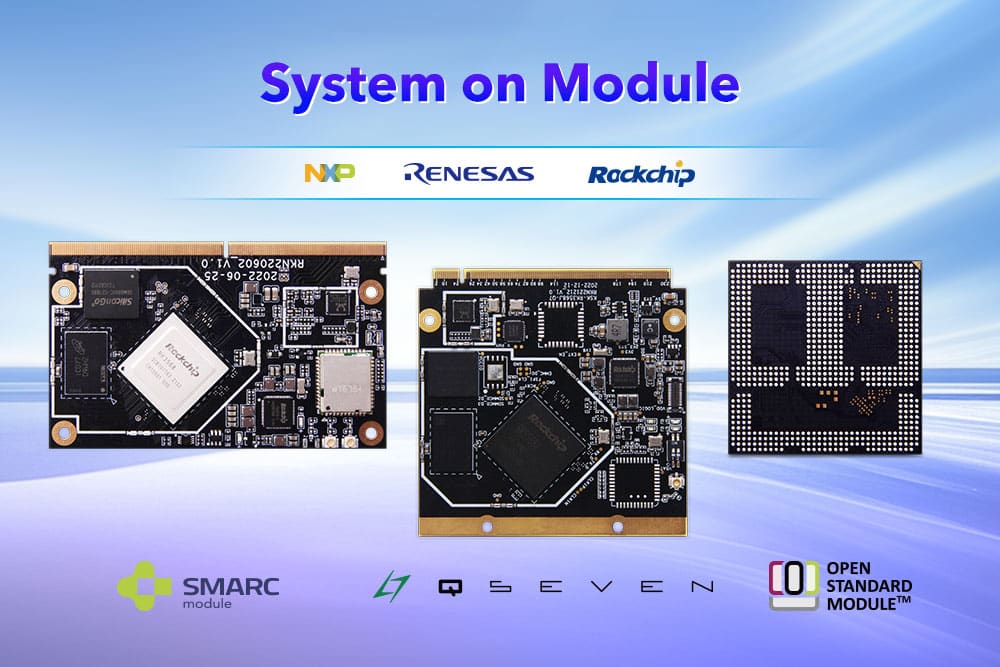
- Standardized formats (e.g., OSM, SMARC, COM Express, Qseven): These offer compatibility across vendors and better ecosystem support.
- Custom designs (e.g., SODIMM-style, proprietary mezzanine connectors): These can be optimized for cost or performance, but lock you into a specific supplier.
System-on-Module connection type refers to the physical interface between the SoM and carrier board for power, data, and signals. It affects replaceability, design complexity, cost, and reliability. Common types include:
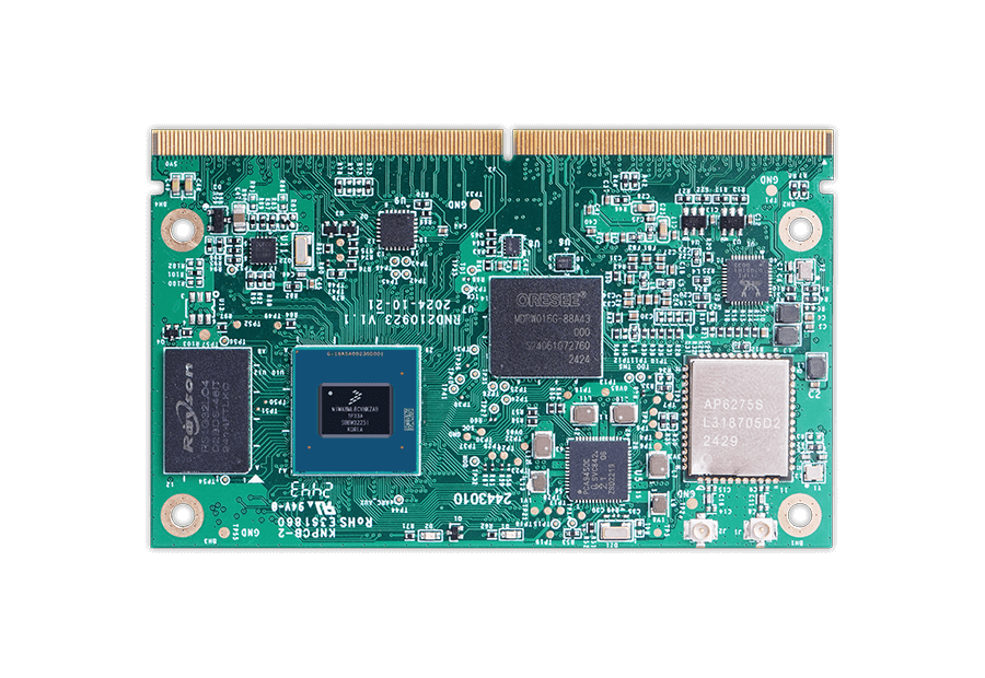
- Edge Connector — Also known as gold-finger or card-edge modules, these are commonly seen in standards like COM Express, SMARC, and Qseven. They’re easy to replace, but their edge connector results in a larger footprint and added thickness due to the connector height.
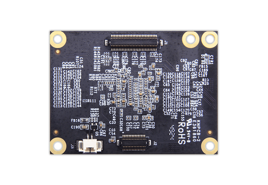
- Mezzanine Connector — Often referred to as board-to-board (B2B) modules, using connectors such as Hirose FX10/FX20 or Samtec QTH/QSH with 100–600 pins. They offer compact, robust connections and are well-suited for high-density or portable designs.
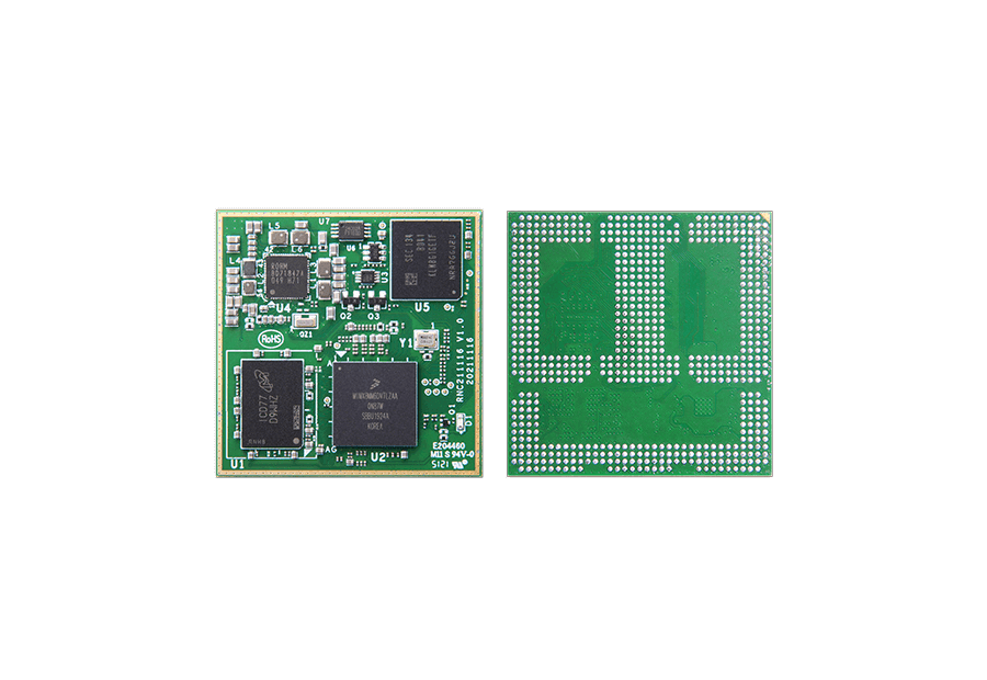
- Solder-down SoMs — Also called LGA or BGA modules, with examples including OSM and custom industrial formats. They are space-efficient and rugged, ideal for automated production environments, but cannot be replaced once soldered.
 |
 |
 |
| Edge Connector | Mezzanine Connectors | Solder-Down |
Choose a format that aligns with your carrier board design constraints and long-term maintainability.
5. Power Consumption and Thermal Design
Make sure the SoM’s power consumption fits your system’s power budget. Power usage varies by workload, so check whether the vendor provides detailed power profiles for typical use cases.
The thermal path matters more than the TDP number.
A module with lower TDP can still fail if heat cannot escape through the carrier board, thermal interface material (TIM), heatsink, and enclosure wall. Copper planes, thermal vias, and solder mask thickness on the carrier board directly influence junction temperature. A poorly designed carrier board with insufficient thermal vias can add 5–10°C to the junction temperature—even with a perfect heatsink.
Critical rule:
If your mechanical engineer is not involved in SoM selection, stop and bring them in immediately. Thermal design is not an afterthought; it is a first-order constraint that determines whether your IP67-rated product survives its first summer in the field.
If your application involves sustained high loads, determine whether passive or active cooling is needed. Some vendors offer heat plates or heatsinks as standard accessories.
6. Software Support (BSP)
A complete and well-maintained Board Support Package (BSP) is essential. It should cover bootloader, kernel, and drivers for your chosen operating system (Linux, Android, RTOS, etc.).
Review:
- Whether the BSP is production-ready or just a demo
- The frequency of updates and bug fixes
- Quality of documentation and developer guides
Inadequate software support can significantly delay project timelines.
7. Supply Chain Reality Check — Beyond the “10-Year Lifecycle” Promise
Vendors routinely advertise 10-year availability guarantees—but these promises often apply only to the main processor, ignoring the volatile lifecycle of onboard DRAM and eMMC flash. When those components go end-of-life, the vendor must change the module design, and your carrier board may break.
Real-world case 1: A future NVIDIA Jetson TX2 module revision introduced new DRAM requiring different hardware strap configurations. Customer carrier boards failed to boot with the revised modules because the original design lacked the required pull-up/pull-down resistor options. Resolution required a physical hardware rework.
Real-world case 2: A custom carrier board for HummingBoard/i.MX6 left the SD3/eMMC power path disconnected because the designer assumed it only powered the carrier’s own eMMC. However, the SoM used that same rail for its onboard eMMC. The system could not boot until the power path was revised and U-Boot re-validated.
Ask every vendor these 3 questions before signing any agreement:
1. “What is your alternate BOM policy for memory components?”
2. “Do you provide a formal Product Change Notification (PCN) at least 12 months in advance?”
3. “What module revisions and memory substitutions have you introduced in the last two years, and what was the carrier-board impact for each?”
Evaluating the SoM Vendor
Selecting a robust, reliable vendor is just as critical as choosing the hardware.
Vendor Reliability
Assess the vendor’s experience and focus:
- How long have they served the embedded market?
- Do they specialize in SoMs, or is it a side business?
- How many SoM families do they maintain?
Established vendors with a long-standing product line are more likely to provide stable supply and consistent support.
In-House Manufacturing
Vendors that manage their own production lines typically offer better control over quality, lead times, and supply chain risks.
In contrast, those who outsource production may face challenges during component shortages or geopolitical disruptions.
Documentation and Design Resources
Thorough documentation shortens integration time. At minimum, the vendor should provide:
- Hardware datasheets and schematics
- Carrier board reference designs
- PCB layout and 3D models
- Signal descriptions and pin maps
Pre-validated design resources help reduce bring-up risks and speed development.
Technical Support and Collaboration
Designing around a SoM often requires collaboration with the vendor. Verify:
- Is there a dedicated support portal?
- Are response times acceptable?
- Can you request design reviews or direct engineering support?
- Are services like schematic validation available?
Helpful, accessible technical support is especially valuable during prototyping and early production phases.
Certification Support
If your application needs regulatory certifications (e.g., FCC, CE, UL), your SoM may be subject to EMC and safety testing.
For wireless modules (Wi-Fi/Bluetooth), using pre-certified SoMs can simplify the certification process. Check whether the vendor can provide relevant documentation and test reports.
Final Thoughts
A System-on-Module is a foundational part of your embedded design. The right choice can simplify development, improve reliability, and future-proof your product. But beyond specs, success depends on the availability, support, and partnership offered by the vendor.
Choose wisely—not just based on features, but based on long-term viability.
FAQ: Questions Engineers Actually Ask About SoM Selection
Q: Can I trust a vendor’s data sheet power consumption numbers?
A: No. Data sheets typically show power under idle or highly optimistic conditions. Always measure power while running your actual workload at maximum operating temperature.
Q: Should I choose an edge-connector or mezzanine connector SoM?
A: Edge connectors (COM Express, SMARC) are easier to replace in the field. Mezzanine connectors (Hirose, Samtec) are more compact and rugged but harder to rework. Choose based on your maintenance strategy.
Q: How do I handle software variations between hardware revisions?
A: Build a bootloader that reads board ID resistors or EEPROM data and loads the correct Device Tree automatically. This avoids maintaining separate software branches per revision.
Q: Is it cheaper to build a custom single-board computer instead of using a SoM?
A: Only if your annual volume exceeds 10,000 units. Below that, the NRE costs for PCB design, RF certification, and BSP maintenance make SoMs the cheaper choice.
Q: What’s the single most common carrier board mistake?
A: Misconfiguring high-speed signal trace impedances and neglecting power supply decoupling near connector pins. This causes intermittent crashes that are extremely difficult to debug.